Prints data on signs. Prints the value of its data pins as text on a sign block when the clock pin (input 0) is set to high. Any sign attached to an interface block will be updated. Signs must be attached before activating the chip and breaking any will cause the circuit to deactivate.
The first sign argument sets the way the data from the chip’s inputs is printed to the sign.
- num - prints input bits as unsigned integer. This is the default data type.
- signed - prints input bits as signed integer.
- unsigned - same as ‘num’
- ascii - prints an ascii character based on the integer value of the input bits.
- hex - same as ‘unsigned’ with hexadecimal representation.
- oct - same as ‘unsigned’ with octal representation.
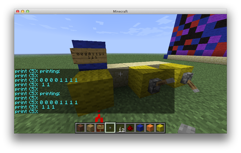
- bin - prints the incoming bits as a series of 0s and 1s.
A second sign argument sets the display mode.
- replace - Whenever the clock pin is triggered any text already on the sign is replaced with the new data. This is the default display mode.
- add - Whenever the clock pin is triggered the new data is added after the text that’s already on the sign. When the sign is full the text is cleared. This mode requires an extra clear pin after the clock pin. When the clear pin is triggered, the all text on the output sign is removed.
- scroll - Works internally as the add mode but displays only a part of the buffered text on one sign line at each moment. This mode also uses a clear pin and in addition requires a scroll pin. When the scroll pin is triggered the part of the text displayed on the sign is updated to start with the next character. Connecting a clock to this pin create a scrolling effect. Once the end of the buffered text is reached the sign will continue scrolling from the beginning of the message.
To build a print chip as a wireless receiver add a channel argument using the syntax #name[:startbit] The channel argument must be the last. In this mode print requires no inputs or outputs. The bit configuration the receiver expects is the same as the physical inputs but without the need for a clock pin. For example, if a chip is in add mode, the 1st channel bit is the clear bit, and all the following bits are data bits.
It’s possible to directly edit the text on the output signs by pointing at the circuit’s activation sign and entering the /rctype <sign text> command. If the circuit is using add or scroll mode the new text will be added to the previous sign text.

I/O setup
- No output pins.
- At least 2 inputs in replace mode. 1 clock trigger and 1 or more data inputs.
- At least 3 inputs in add mode. 1 clock trigger, 1 clear pin and 1 or more data inputs.
- At least 4 inputs in scroll mode. 1 clock trigger, 1 clear pin, 1 scroll pin and 1 or more data inputs
- Wireless mode doesn’t require any inputs.
Sign text
print[data type](num by default)[display mode](replace by default)[#channel](optional)
Version history: Added to BasicCircuits 0.1
